You test a sprinkler solenoid with a multimeter set to resistance (ohms). Disconnect the two solenoid wires from the controller wiring at the valve box and touch the multimeter probes to the two solenoid wire terminals. A reading between 20 and 60 ohms indicates a functional solenoid — the exact healthy range varies by brand, but this window covers most Rainbird, Hunter, and Toro residential solenoids. A reading near zero (short circuit) or no reading at all (open circuit / infinite ohms) confirms the solenoid has failed and needs replacement. If you do not have a multimeter, there is a no-tool field test using the manual bleed that tells you in about two minutes whether the solenoid or the wiring is the source of a zone failure — that test is described in the next section.
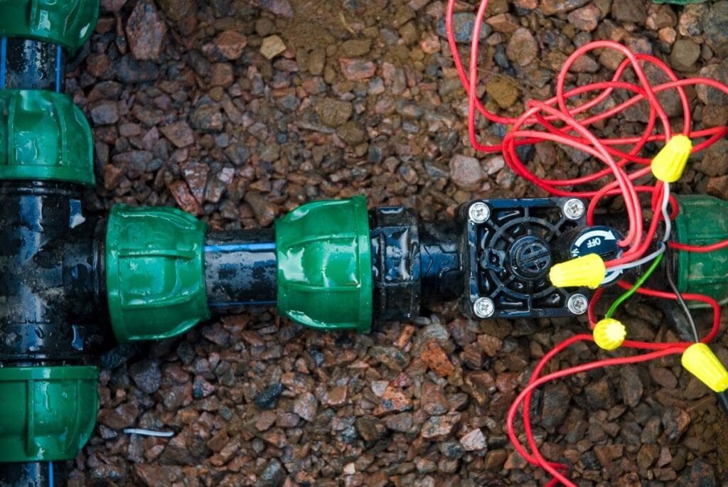
A zone valve solenoid with zone wires and wire connector nuts visible — this is what you are testing when you diagnose a solenoid. The solenoid body attaches to the valve body with a quarter to half turn and connects to the irrigation controller via two low-voltage wires (24V AC): a common wire (typically white) shared across all zones, and a zone-specific wire (typically color-coded by zone). Testing the solenoid means measuring the electrical resistance of the coil windings inside the solenoid body between these two wire terminals. On Tulsa-area systems, spring startup is the most common time to find a failed solenoid — freeze events over winter damage the internal windings without any visible external evidence of failure.
The Manual Bleed Test: No Tools Required
Before getting a multimeter, this two-minute field test tells you whether the zone failure is electrical (solenoid or wiring) or mechanical (valve diaphragm). It works on any solenoid valve brand:
- Locate the valve for the non-functioning zone in the valve box. If you have multiple valves, identify the correct one by running each functioning zone from the controller and watching which valves click on — the remaining valve that never activates is the one for your dead zone.
- Open the manual bleed on the problem valve with the irrigation water supply on. On Rainbird valves, there is typically a small bleed screw on the side of the valve body. On Hunter valves, turn the solenoid counterclockwise one quarter turn. On Toro valves, check the side of the valve body for a bleed port.
- Observe whether the zone runs with the manual bleed open. If heads rise and spray normally, the valve body and diaphragm are functional — the problem is electrical (solenoid or wiring). If the zone does not run even with the manual bleed fully open, the valve diaphragm has failed and the problem is mechanical regardless of what the solenoid tests show.
- Close the manual bleed. An open bleed runs the zone continuously until closed.
If the manual bleed confirms the zone can run (the problem is electrical), the solenoid is the most likely single component failure and the multimeter resistance test described below confirms or rules it out before you buy a replacement.
The Multimeter Resistance Test: Step by Step
A basic multimeter — available for $10 to $20 at hardware stores throughout Tulsa, Broken Arrow, and the surrounding area — is the definitive tool for solenoid testing. The test takes about five minutes at the valve box:
- Set the multimeter to resistance mode (labeled with the omega symbol — Ω). Most basic multimeters have a single resistance range that works for solenoid testing; if your meter has multiple ohm ranges, select the 200-ohm range.
- Open the valve box and locate the two wires connected to the solenoid. These are the solenoid pigtail wires — short wires coming directly from the solenoid body that connect to the longer irrigation wiring via wire connector nuts inside the box.
- Disconnect the solenoid pigtail wires from the connector nuts. You are isolating just the solenoid for testing — if you test with the controller wiring connected, you are measuring the wiring circuit, not the solenoid alone.
- Touch one multimeter probe to each solenoid terminal (one probe per pigtail wire end). Polarity does not matter — the resistance reading is the same regardless of which probe touches which terminal.
- Read the multimeter display. A healthy solenoid reads in the 20 to 60 ohm range. The specific healthy range varies by brand and model — most Rainbird and Hunter residential solenoids read between 24 and 53 ohms when functional. If you want exact specifications, the brand and model number are typically stamped on the solenoid body.
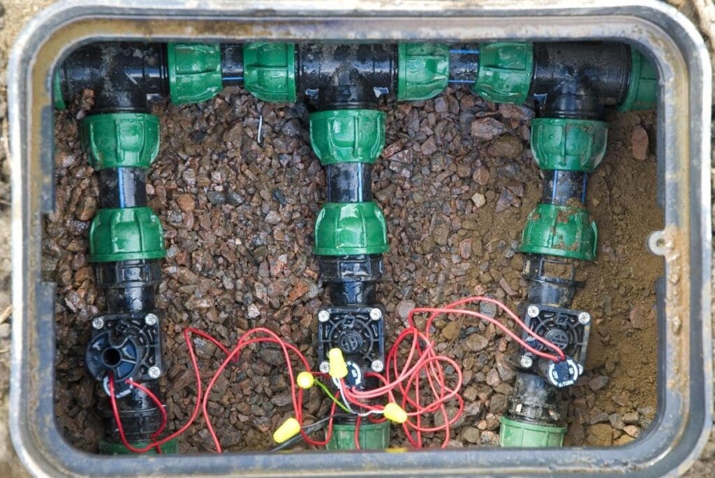
A valve manifold with multiple solenoids inside a valve box — each solenoid controls one irrigation zone. When testing multiple solenoids on the same manifold, disconnect and test each solenoid individually by its pigtail wires to ensure you are reading only that solenoid’s resistance, not the combined resistance of the wiring circuit. On Tulsa-area systems with manifolds like this one, testing all solenoids during a spring startup inspection takes about 15 minutes with a multimeter and is an efficient way to identify any zone that failed over winter before running the irrigation season.
Reading the Results
What the multimeter reading tells you:
| Multimeter Reading | What It Means | Next Step | Notes |
| 20-60 ohms (within brand spec) | Solenoid is electrically sound | Solenoid is not the cause of the zone failure — check wiring, controller terminal, and valve diaphragm next | Most Rainbird and Hunter solenoids: 24-53 ohms; Toro varies by model — confirm with spec sheet |
| Below 10 ohms (near zero) | Internal short circuit — windings shorted together | Replace solenoid immediately; do not repeatedly run zone as short can damage controller | Short circuits can sometimes damage the controller terminal; test the terminal after solenoid replacement |
| Infinite ohms / OL / no reading | Open circuit — winding wire broken internally | Replace solenoid | Most common failure after freeze events — ice damage breaks the internal winding wire |
| 60-200 ohms (above spec) | High resistance from corrosion or partial winding damage | Replace solenoid; it may work intermittently but will fail completely | Common on older solenoids with corroded terminal connections; clean terminals and retest before replacing |
| Reading fluctuates / unstable | Intermittent connection — internal damage or corrosion at terminals | Replace solenoid; intermittent failures are difficult to diagnose at field conditions | Wiggle the solenoid body while testing — if reading changes, the internal connection is failing |
Testing Without a Multimeter: The Swap Test
If you do not have a multimeter and cannot get one quickly, the swap test uses a known-good solenoid from a functioning valve to confirm whether the suspect solenoid is the failure:
- Identify a functioning zone on the same valve manifold with a solenoid of the same brand and model as the suspect zone. Rainbird solenoids are not interchangeable with Hunter solenoids — the swap only works within the same brand family.
- Remove the solenoid from the functioning valve by turning it counterclockwise until it releases from the valve body. Most residential solenoids require a quarter to half turn to release.
- Thread the known-good solenoid onto the suspect valve body. Connect its pigtail wires to the zone wiring in the valve box using the wire connector nuts.
- Activate the suspect zone from the controller. If the zone now runs normally, the original solenoid was the failure. If the zone still does not run with the known-good solenoid installed, the problem is in the wiring or controller terminal for that zone, not the solenoid.
- Reinstall all solenoids in their original positions after testing. Label which solenoid came from which valve if you remove multiple solenoids to avoid mixing them up.
The swap test is slower than a multimeter test and requires handling functioning valve components, but it is a reliable confirmation method when test equipment is not available.
Why Solenoids Fail in Tulsa-Area Systems
Understanding the most common causes of solenoid failure in this region helps with both timing expectations and prevention:
Freeze damage. The most common cause of solenoid failure in Oklahoma is freeze damage during winter. Water retained inside the solenoid housing from the end of the irrigation season freezes and expands, cracking the internal coil windings. The external solenoid body typically shows no visible damage — it looks identical to an undamaged solenoid — but the multimeter test reveals an open circuit (infinite ohms) where the winding wire has broken. Solenoids damaged this way in December or January often do not show up as zone failures until spring startup, when the system is pressurized and the controller sends the first signal to the failed solenoid. On Tulsa-area systems that were not properly winterized, spring startup routinely reveals one or more solenoid failures from the preceding winter.
Age and moisture exposure. Solenoid coil windings gradually degrade from repeated heat cycling and moisture exposure in the valve box environment. Solenoids on residential systems in the Tulsa area that are 15 to 20 years old — which includes many original components on systems installed in the early 2000s construction boom across Broken Arrow, Bixby, and Jenks — are reaching the end of their reliable service life. A solenoid that tests at the high end of the resistance range (50 to 80 ohms) is approaching failure; replacement is appropriate before it fails completely mid-season.
Corrosion at wire terminals. Tulsa’s hard water leaves mineral deposits throughout the irrigation system, including on wire connector nuts and solenoid terminal connections in valve boxes that have experienced water intrusion. Corroded connections create increased resistance at the terminal point that the multimeter will detect as an elevated ohm reading even if the solenoid coil windings are intact. Before concluding a solenoid with a high resistance reading needs replacement, disconnect the pigtail wires, clean the bare wire ends with sandpaper or a wire brush to remove corrosion, and retest. A reading that drops to the normal range after cleaning indicates the solenoid is fine and the connection was the issue.
Voltage surge damage. Lightning is a real risk to irrigation system electronics in Oklahoma. A nearby lightning strike or a significant utility power surge can damage solenoid coil windings — producing either an open circuit (winding burned out) or a short circuit (windings fused together). Short circuit readings on a solenoid that was working normally before a storm event are a reliable indicator of surge damage. The same surge that damaged the solenoid may have also damaged the controller terminal — test the terminal after replacing a surge-damaged solenoid to confirm it is still outputting the correct 24V AC signal.
| Solenoid Resistance Reference by Brand (Approximate)Rainbird: 20-60 ohms (most models 24-48 ohms)Hunter: 20-60 ohms (most models 26-53 ohms)Toro: 30-60 ohms (varies by model — confirm on solenoid label or manufacturer spec sheet)Irritrol: 20-60 ohmsK-Rain: 20-60 ohms Important: solenoid resistance specs vary by model within each brand.Always confirm the specific healthy range for your solenoid model when exact diagnosis matters.The 20-60 ohm window is a reliable field test range — readings outside this window ineither direction indicate solenoid failure regardless of the exact brand spec. |
What to Do After Confirming a Bad Solenoid
Replacing a failed solenoid is one of the fastest irrigation repairs there is. The process:
- Turn off the irrigation controller before removing the solenoid. There is no need to shut off the main water supply — the solenoid sits on top of the valve body and does not contact the water flow path when being replaced. You are working with low-voltage wiring only.
- Turn the solenoid counterclockwise until it releases from the valve body. Most residential solenoids require one quarter to one half turn. Do not force it if it feels stuck — apply upward pressure while turning rather than torquing at an angle.
- Disconnect the old solenoid pigtail wires from the connector nuts in the valve box.
- Purchase a replacement solenoid matching your valve brand. Replacement solenoids for Rainbird, Hunter, and Toro are available at hardware stores throughout the Tulsa area. Generic universal solenoids are available and physically fit many valve bodies, but brand-specific replacements are recommended for reliability — the coil specifications are matched to the valve design.
- Thread the new solenoid onto the valve body clockwise until snug. Hand tight is correct — do not over-tighten.
- Connect the new solenoid pigtail wires to the zone wiring using fresh wire connector nuts. If the original connectors were not waterproof direct-burial connectors, upgrade to waterproof connectors at this step — standard wire nuts in the valve box environment degrade and corrode, causing the type of high-resistance connection issues described above.
- Test from the controller. Activate the zone and confirm it runs normally before closing the valve box.
Solenoid replacement cost: $10 to $25 for the part at retail. Time: 10 to 15 minutes per valve. This is one of the most accessible irrigation repairs for homeowners who are comfortable with basic electrical connections and can locate their valve boxes.
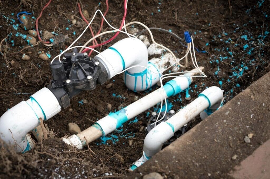
A zone valve installation with PVC fittings, solenoid body, and zone wiring in an excavated area — this type of valve installation with fresh PVC cement marks visible is typical of a new zone valve being installed after the original valve body was too damaged to repair. When a solenoid test confirms the solenoid has failed but solenoid replacement does not restore zone function, the next test is the valve diaphragm. When both solenoid and diaphragm appear functional but the zone still does not operate, the wiring between the controller and the valve is the remaining diagnostic area.
When Solenoid Replacement Does Not Fix the Zone
If replacing a confirmed bad solenoid does not restore zone function, the diagnosis moves to the next most likely cause. Work through this sequence:
- Wiring continuity test. With the new solenoid installed, use the multimeter to test resistance between the zone wire at the controller terminal and the common wire at the controller terminal. With the solenoid connected at the valve box end, a reading in the 20-60 ohm range confirms the wiring is intact and the zone signal path from controller to solenoid is functional. An infinite reading (open circuit) indicates a wire break somewhere in the run between the controller and the valve.
- Controller terminal test. With a working solenoid installed and wiring confirmed intact, verify the controller is outputting 24V AC on the zone terminal. Set the multimeter to AC voltage, connect one probe to the zone terminal and one to the common terminal on the controller, and activate the zone. A reading of 24 to 28V AC confirms the controller is sending the correct signal. No reading or a reading significantly below 24V indicates a failed controller terminal.
- Valve diaphragm inspection. If electrical testing confirms the solenoid, wiring, and controller are all functioning, the valve diaphragm is the remaining mechanical suspect. The manual bleed test (described at the top of this article) confirms whether the valve body can open at all — if it cannot open with the manual bleed fully engaged, the diaphragm has failed regardless of the electrical system status.
Irrigation Diagnosis and Repair in the Tulsa Area
For more than 25 years, Complete Lawn Care has been diagnosing and repairing irrigation systems throughout Tulsa, Broken Arrow, Bixby, Jenks, Owasso, and Sand Springs. Our irrigation team approaches every zone failure with a systematic process — solenoid, wiring, controller, valve diaphragm — rather than replacing components at random until something works. The science-based, intentional approach that guides our lawn care program applies equally to irrigation service.
With over 25 years of experience, we combine proven results with a data-driven approach to irrigation service. We have seen every failure pattern common to Oklahoma’s climate — from spring solenoid failures after freeze events to wiring damage from landscaping work to valve diaphragm failures on systems that have been in service since the early 2000s. We find the actual cause and fix it correctly the first time.
Experience tells us what to do. Science tells us when and why. Every service call is intentional.
Zone Not Running on Your Tulsa-Area System?
Contact Complete Lawn Care at completelawncaretulsa.com or call (918) 605-4646. We will diagnose it accurately and fix it right — serving Tulsa, Broken Arrow, Bixby, Jenks, Owasso, and Sand Springs.
Experience. Science. Intentional Lawn Care — That’s the Complete Lawn Care Difference.